Building a smarter plant
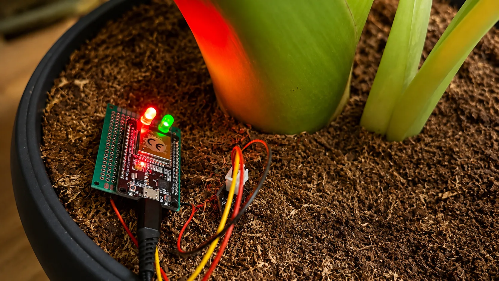
For about a year, I had an ESP32 and a couple of capacitive soil moisture sensors sitting in a drawer. I had already tried getting one to work once before, but eventually gave up after running into problems I couldn’t figure out.
A few days ago I decided it was time to give it another shot.
Back to the breadboard
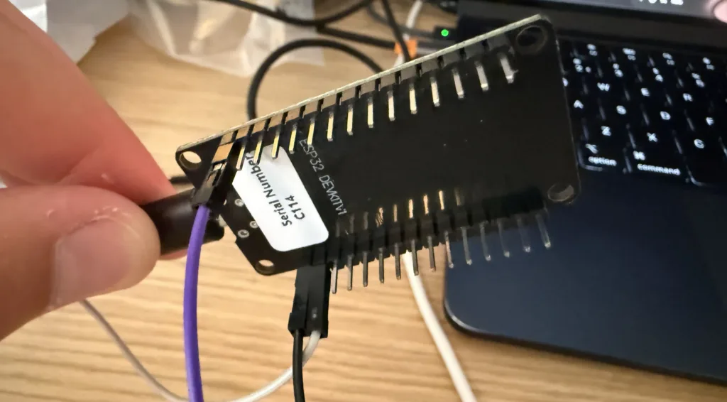
The first thing I discovered was that the sensor I had originally been testing was simply faulty. Luckily, I had another one lying around.
This one looked much more promising. It returned sensible values at first, but after a minute or two every reading slowly drifted back towards zero. My first thought was that I’d connected it to the wrong GPIO pin, so I tried a couple of different analog inputs. The behaviour stayed exactly the same.
Eventually I stumbled upon the actual cause.
The documentation for the sensor suggests powering it from 3.3V, but on my ESP32 it only became stable once I connected it to VIN (5V) instead. As soon as I switched the power supply, the readings stopped drifting and finally became reliable.
Calibrating the sensor
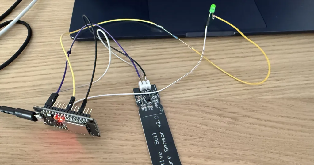
With stable readings, I could finally calibrate the sensor.
The measurements ended up looking roughly like this:
| Condition | Reading |
|---|---|
| Air | 2200–2350 |
| Dry soil | 1850–2000 |
| Moist soil | 1400–1500 |
| Freshly watered | 400–600 |
Instead of simply showing “wet” or “dry”, I wanted a bit more feedback. I ended up defining four moisture levels:
- 🟢 Healthy
- 🟢🔴 Getting dry
- 🔴 Water needed
- 🔴 Flashing red — water me now
At first these states only existed in Home Assistant, but I thought it would be nice if the plant itself could tell me how it was doing.
That meant adding two LEDs.
The hardware ended up being surprisingly simple:
ESP32 DevKit

Soil moisture sensor

├── VCC → VIN (5V)

├── GND → GND

└── AO → GPIO34

Green LED

└── GPIO25 → 220Ω resistor → LED → GND

Red LED

└── GPIO26 → 220Ω resistor → LED → GND
My first soldering project
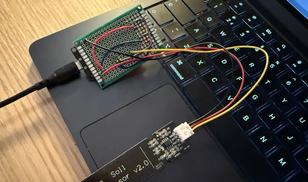
Everything started as a pile of jumper wires on my desk. Only after I knew the hardware and software worked reliably did I solder everything together.
This was also my first time soldering.
My first few solder joints definitely weren’t pretty, but once I started using flux everything suddenly became much easier. It’s one of those things that immediately makes you wonder why you didn’t use it from the start.
The final result certainly isn’t perfect, but it’s solid enough to live inside a plant pot.
From Arduino to ESPHome
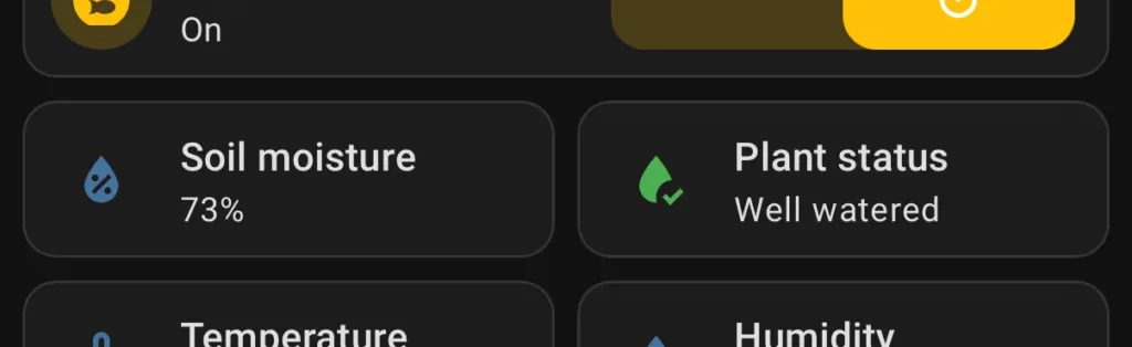
Originally the LEDs and sensor were driven by a small Arduino sketch. Once everything worked, I migrated the project to ESPHome so I could update the ESP32 over Wi-Fi instead of pulling it out of the planter every time I wanted to tweak a threshold.
There were a couple of moments where I thought I’d broken something. At one point the LEDs kept reporting dry soil, even with the sensor sitting in a glass of water. In the end, nothing was actually wrong — the median filter was simply averaging older measurements, so it took a while before the new reading became visible.
The sensor now reports its moisture level to Home Assistant while the LEDs provide the same status directly on the plant. Even without opening the dashboard, I can immediately see whether it needs watering.
For now, the ESP32 is still sitting loose inside the planter, so I mostly just have to remember not to pour water directly over it.
Designing and 3D printing a proper enclosure will probably be the next step.
Components
- ESP32 DevKit
- Capacitive Soil Moisture Sensor
- 2× 220Ω resistors
- Green LED
- Red LED
- Stripboard
- Jumper wires